These notes relate to the stresses and strains existing in thick walled cylinders when subject to internal and external pressures. The notes include the analysis of two or more cylindrical parts, assembled by press fitting or shrinking, resulting in an interference fit between the parts. The equations resulting enable estimates of the forces need to assemble and separate the parts and the maximum torque which can be transmitted by the assembly
Members of excelcalcs.com can upload a spreadsheet including all of the derived equations below at ExcelCalcs.com calculation Thick cylinders
Symbols / Units
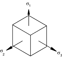
Tensile stresses are considered positive and compressive stresses are negative.
The pressures p, p 1, p 2 & p f are negative
| p = radial stress (compressive) (N/m2) p 1 = Internal pressure (N/m2) p 2 = External pressure (N/m2) p f = Interface pressure (press fit)(N/m2) σ r = radial (normally compressive)(N/m2) σ t = tangential stress (normally tensile)(N/m2) σ a = axial/longitudonal stress (normally tensile)(N/m2) E = Young's moudulus of elasticity (N/m2) υ = Poissan's ratio υ h = Poissan's ratio hub υ s = Poissan's ratio shaft d = diameter at point or analysis (m). d 1= inside diameter of cylinder (m). d 2= outside diameter of cylinder (m). d f= interfacediameter of cylinder (press fit)(m). |
r = radius at point or analysis (m). r 1= inside radius of cylinder (m). r 2= outside radius of cylinder (m). r f= interface radius of cylinder (press fit)(m). εr = radial strain εt = tangential strain εa = axial /longitudinal strain u = radial deflection (m) us = radial deflection of shaft (m) uh = radial deflection of hub(m) ut = radial deflection of hub and shaft(m) δr h = Radial increase in hole (m) δr s = Radial decrease in hole (m) |
Initial Assumptions
The following relationships are assumed for the strains ε1,ε2, ε3 associated with the stress σ 1, σ 2 and σ 3.
υ = Poisson's ratio.
Reference Notes on stress and strain
ε1 = σ 1 /E - υσ 2 /E - υσ 3 /E
ε2 = σ 2 /E - υσ 1 /E - υσ 3 /E
ε3 = σ 3 /E - υσ 1 /E - υσ 2 /E
Thick Cylinder basics
Consider a thick cylinder subject to internal pressure p 1 and an external pressure p2. Under the action of radial pressures on the surfaces the three principal stress will be σ r compressive radial stress, σ t tensile tangential stress and σ a axial stress which is generally also tensile. The stress conditions occur throughout the section and vary primarily relative to the radius r. It is assumed that the axial stress σ a is constant along the length of the section...This condition generally applies away from the ends of the cylinder and away from discontinuities.
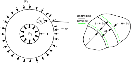
Consider a microscopically small area under stress as shown. u is the radial displacement at radius r . The circumferential (Hoop) strain due to the internal pressure is
![]()
At the outer radius of the small section area (r + δr ) the radius will increase to (u + δ ). The resulting radial strain as δr -> 0 is
![]()
Referring to the stress/strain relationships as stated above. The following equations are derived.
Basis of equations...
σ r is equivalent to σ 1...
σ t is equivalent to σ 2...
σ a is equivalent to σ 3...
derived equations
Eq. 1)......E ε a = σ a - υσ t - υσ r
Eq. 2)......E.ε t = E.u/r = σ t - υσ a - υσ r
Eq. 3)......E.εr = E.du/dr = σ r - υσ t - υσ a
Multiplying 2) x r
Eu = r ( σ t - υσ a - υσ r )
differentiating
Edu/dr = σ t - υσ a - υσ r + r. [ dσ t /dr - υ.( dσ a / dr ) - υ.( dσ r / dr ) ] = σ r - υσ t - υσ a ..( from 3 above )
Simplifying by collecting terms.
Eq. 4)........(σ t - σ r ). ( 1 + υ ) + r.(dσ t/ dr ) - υ.r.(dσ a / dr ) - υ.r.(dσ r / dr) = 0
Now from 1) above since ε a is constant
dσ a / dr = υ.(dσ t / dr + dσ r / dr )
Substituting this into equation 4)
( σ t - σ r )( 1 + υ ) + r ( 1 - υ 2 ).( dσ t/dr ) - υ.r.( 1 + υ )( dσ r / dr ) = 0
This reduces to..
Eq. 5).....σ t - σ r + r( 1 - υ ).(dσ t / dr ) - υ.r.(dσ r / dr ) = 0
Now considering the radial equilibrium of the element of the section. Forces based on unit length of cylinder
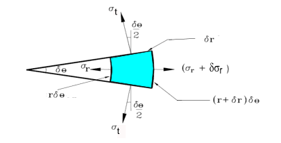
(σ r + δ σ r )(r + δ r)δθ - σ r r δ θ - 2σ t δ r.sin [(1/2) δ θ ] = 0
In the limit .sin [(1/2) δ θ ] - > [(1/2) δ θ ] and neglecting small products the equation reduces to..
σr δ r + δσr.r -σ t δ r = 0... and as δ r --> 0 then σr. d r + dσr.r -σ td r = 0...as δ and this results in..
Eq.6)....σr + r. (d σr/dr ) = σ t
Now eliminating σ t by substituting eq 6 into eq 5)
σr + r. (d σr/dr ) - σ r + r( 1 - υ ).(dσ t / dr ) - υ.r.(dσ r / dr ) = 0
r( 1 - υ )(d σr/dr ) + r( 1 - υ ).(dσ t / dr ) = 0
simpifying to
(d σr/dr ) + (dσ t / dr ) = 0
Integration of this equation results in
Eq.7).... σr + σ t = 2.A (constant of integration.)
substituting this into equation 6 to eliminateσt
σr + r. (d σr/dr ) = 2.A - σr
Therefore
2.A = 2. σr + r. (d σr/dr ) which is equivalent to 2.A = (1 /r ). d ([ r2. σ r ]/dr )
therefore 2.A.r = (d[r2.σr]/dr )
Which on integrating gives σr.r2 = A..r2 + B
with resulting
Eq 8) σr = A + B / r 2 and substituting this into Eq. 7)
Eq 9) σt = A - B / r 2
General Equation for Thick Walled Cylinder
The general equation for a thick walled cylinder subject to internal and external pressure can be easily obtained from eq)8 and eq) 9 as follows.
Consider a cylinder with and internal diameter d 1, subject to an internal pressure p 1. The external diameter is d 2 which is subject to an external pressure p 2. The radial pressures at the surfaces are the same as the applied pressures therefore
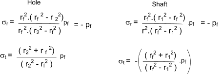
σ r = A + B / r 2
σ t = A - B / r 2
The radial pressures at the surfaces are the same as the applied pressures therefore
- p1 = A + B / r 12
-p2 = A + B / r 22
![]()
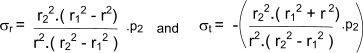
The resulting general equations are known as Lame's Equations and are shown as follows
|
|
If the external pressure is zero this reduces to
![]()
If the internal pressure is zero this reduces to
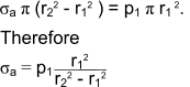
The longitudonal stress σ a for a thick walled cylinder with closed ends is simply obtained from the equilibrium equation for a traverse section
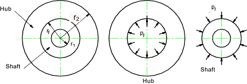
Interference Fit
Consider a press fit of a shaft inside a hole. The compression of the shaft and the expansion of the hub result in a compressive pressure at the interface. The conditions are shown in the figures below
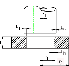
The radial interference δr 1 = the sum of the shaft deflection δr s and the hole deflection δr h
The longitundonal pressure and hence σ a are assumed to be zero and the internal pressure in the shaft hole and the external pressure outside the hub are also assumed to be zero. (ref. to equation 2)
Eq. 2)......E.ε t = E.u/r = σ t - υσ a - υσ r = σ t - υσ r
Radial Increase in Hole diameter = u. h = ( r f / E h ) (σ t - υ h.σ r ) ... The condition is equivalent to a thick cylinder with zero external pressure
Radial decrease in shaft diameter = u s = - ( r f / E s ) (σ t - υ s.σ r ) ... The condition is equivalent to a thick cylinder with zero internal pressure
Total interference u t = u h + u s
The displacement of the hole u h and the shaft u s are as follows.
( (Hole r1 = r f p f = p 1 ) ( Shaft r2 = r f p f = p 2 )
![]()
The total interference is therefore equal to
![]()
If the hub and the shaft are the same material with the same E and σ the equation simplifies to
![]()
The normal engineering application is when the shaft is solid i.e. r1 = zero therefore the equation further simplifies to
![]()
It is often required to determine the interface pressure when the radial interference u t is known (This is half the shaft interference) i.e to determine the torque which can be transmitted or the force require to make or separate the interference joint.
![]()
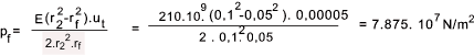
Example calculation of torque transmitted by an interference fit
Consider a steel shaft 100mm dia. pressed into a ring which has and OD of 200mm. The length of the hole is 50mm . The interference = 0,1mm The assumed coefficient of friction μ = 0,15. The hub and shaft are both steel with E = 210.109 N/m2. Poissens ratio υ = 0,3.
![]()