Below are identified various types of positive displacement motors with notes identifying operating information. These notes and sketches are rudimentary in nature and are provided to show the principles involved in the designs. For detailed notes on the design and performance it is advised the the manufacturers literature is referenced.
Basic Calculations relating motor fluid flow, power and, shaft torque are found on my webpage. Hydraulic Calcs
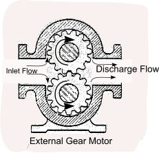
External Gear Motor
The motor includes two gears one gear is includes the drive shaft. The motor bearings are generally provided with internal bearings and packed glands or mechanical seals. The most popular gear types are straight spur. These can be noisy and subject to vibration if they are not manufactured to high standards.
These motors are reliable low cost units which can be run for long periods if operated correctly. They have good high pressure operating characteristics. Close tolerances are required between the internal components for the motor to operate effectively
The gear motor has moderate volumetric and overall efficiency
These motors can operate with fluid pressures of up to 200 bar. For pressures above 50 bar the motors have to be specially designed with hydraulic balancing.
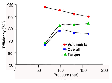
Approx Efficiencies of a typical gear pump /motor
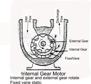
Internal Gear Motor
The pump is based on an external gear located within, and meshing with, a larger internal gear. A crescent vane is included to seperate the inlet volume from the discharge volume between the two gears. The hyddraulic fluid enters enters the inlet volume and the pressure tend to expand the volume which results in the gears rotating. At a certain point in the rotation the volume is connected to the outlet port and as the gears continue to rotate the fluid is force out to the discharge route. the.
The internal gear motor has similar characteristics to the external gear motor. The motor is smoother in operation.< The internal gear motor is however more complicated and expensive to manufacture and maintain.
The internal gear pump can operate at pressures of 200 barg.
Note: The Gerotor hydraulic motor is basically the internal gear motor without the crescent vane. Gerotor motors are one of the most common types of muli-lobe motors whose operation is quite similar to that of an internal gear motor. The inner gear has one tooth less than the outer gear, and the volumetric displacement is determined by the space formed by the extra tooth in the outer gear. The tips of the inner and the outer lobes make contact to seal the inlet and discharge chambers from each other.
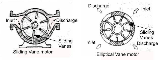
Sliding Vane Motors
The vane motor includes a ring mounted inside a cylindrical case The ring includes a number of radial slots in which are located sliding vanes. The ring is mounted eccentric to the case and the vanes are designed to press against the inside wall of the case. The vanes are forced against the wall by hydraulic pressure or spring force or due the centrifugal force resulting as the ring is rotated.
The fluid flow at pressure is use to rotate the ring and liquid flow into compartments between the vanes and the case inner circumference. The pressure of the liquid causes the ring to rotate to increase the space trapped between the vanes and the case. As the space is reduced as the ring rotates the fluid is discharged.
The older designs of vane motors are based on an eccentric ring as described above . These are not hydraulically balanced and are thus limited in the hydraulic pressure which can be developed. More modern designs include for an elliptical inner ring which results in two pressure cycle per revolution. These pumps can develop much higher pressures at high rotational speeds.
The vanes outer edges are subject to continuous wear and the vanes need to be replaced after periods of continuous use. Modern motors are designed for convenient maintenance by having the internal components design as cartridges.
These motors are smooth operating and have higher efficiency compared to gear motors. Certain designs can tolerate significant vane wear. (carbon vanes)
This type of motor can operate at pressures of up to 200 barg.
The principles of the adjustable displacement vane type hydraulic motor are illustrated in the sketch below

Approx Efficiencies of a typical vane pump /motor
Piston Motors General Notes
The motors are extensively used for power transfer applications in the off shore , power transmission , agricultural, aerospace and construction industries,.. to list just a few. All of these motors work on a similar principle.
The motor includes a block with a number of symmetrically arranged cylindrical pistons around a common centre line. The pistons are caused reciprocate in and out under the action of a Separate fixed or rotating plate (axial Pistons) or and eccentric bearing ring (radial pump) or some other mechanical feature. Each piston is interfaced with the inlet and outlet port via a special valve arrangement such that as it moves out of its cylinder under fluid pressure and as it moves back it pushes the fluid out. The motors are engineered to allow rotational speeds from less the 0,5 RPM to over 25,000RPM.
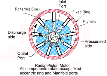
Radial Piston Motor.
Radial Piston motors include a rotating cylinder containing equally spaced radial pistons arranged radial around the cylinder centre line. A springs pushes the pistons against the inner surface of an encircling stationary ring mounted eccentric to the cylinder. The fluid flow at pressure causes the pistons to move out,resulting in rotation, for half of a revolution and the pistons move in ,driving the fluid out during the other half. The greater the ring eccentricity the longer the pistons stroke and the less the rotation speed per unit fluid flow rate.
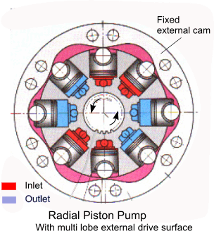
A variation to this principle is shown with an internal shaped cam replacing the eccentric ring this results in the pistons making a number of strokes per revolution of the shaft resulting in smoother more efficient motion.
|
|
|
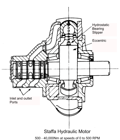
A variation of the radial piston motor is the Staffa motor as shown below. For this type of motor the radial pistons are arranged in the outer case and move against an eccentric section of the rotating shaft. This motor is produced in a number of sizes enabling high torques at low speeds.
Swashplate Motors.
Swashplate motors have a rotating cylinder containing parallel pistons arranged radially around the cylinder centre line. A spring pushes the pistons against a stationary swash plate located at one end of the cylinder , which sits at an angle to the cylinder. The fluid pressure causes the pistons to move out during half a revolution and pistons drive the e fluid out during the other half. The greater the swashplate angle relative to the cylinder centre line the longer the pistons stroke and the less the rotation speed per unit fluid flowrate.

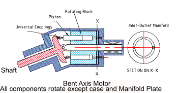
Bent Axis motors.
Bent axis piston motors have a rotating cylinder containing parallel pistons arranged radially around the cylinder centre line. The pressure in the fluid causes the pistons to reciprocate over a stroke based on the relative angle of the shaft and cylinder. The motion of the pistons results in the rotation of the shaft. The cylinder is driven by an shaft which is arranged at an angle to the cylinder axis. The shaft includes a flange with a mechanical connection to each piston. The greater the angle of the cylinders to the shaft axes the longer the pistons stroke and the less the rotation speed per unit fluid flowrate.
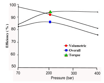
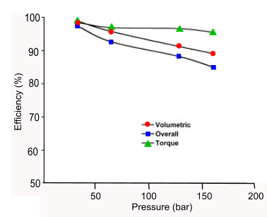
Approx Efficiencies of a typical piston pump /motor
Summary Table
| Type | Max Speed | Min Speed | Pressure range |
Running Efficiency |
Variable option |
Duty | Cost | Flow Range |
| RPM | RPM | bar | % | - | - | - | litres.min | |
| Gear | 2500 | 500 | 0-200 | 80ñ90 | No | Light | Low | 5-500 |
| Int Gear | 2500 | 500 | 0-200 | 70-85 | No | light | Low | 5-750 |
| Gerotor or Geroller | 350 | 25 | 0-200 | Fair | No | Light | Low | Low |
| Vane | 2000 | 200 | 0-200 | 80ñ95 | Yes | Light | Medium | 5-300 |
| Axial | 12000 | 100 | 0-400 | 90ñ98 | yes | Heavy | Medium/High | 5-750 |
| Radial | 12000 | 0 | 0-400 | 85ñ95 | Yes | Heavy | Medium | 5-750 |